Table of Contents
1.3: The HLS Test Bench
Writing and debugging code for an FPGA can be a daunting task. Luckily, when we create a design in HLS, we have the benefit of being able to test it within the HLS environment to see how it will behave.
1.3.1: Our Test Bench File
To begin with, take a look at the file TestGetCentroid.cpp. We're not going to go into too much detail with this file since it's pretty straightforward stuff. We'll just touch on a few important points and some syntax/rules unique to HLS.
Basically, the program in this file is going to read the data from IndexFile.txt and populate the input stream and array to test the algorithm we've specified in our top level function: GetCentroid. You can see where we call the function on the line
GetCentroid(inputStream, IndArrIn, &CentroidOut);
The input arguments are defined with the types that match the ones in our function definition:
		                 fp_data_t IndArrIn[WAVESIZE];

                         fp_data_t CentroidOut;

		                 hls::stream<uintSdChIn> inputStream;
Also note how we are packing two 16-bit values into one 32-bit data type in order to put it in our HLS stream, as we discussed in the previous section.
		                 // Create a pointer to a 32 bit unsigned integer and point that to the short array

		                 uintSdVal *value;

		                 value = (uintSdVal*)(&WaveData[NUMCHANNELS*i]);


		                 // Now read this into the stream

		                 valIn.data = *value;

		                 inputStream << valIn;
Before going into the details of how to test our algoritm, it is especially important to note that you MUST INCLUDE the last line (the comment is not necessary)!!!
		                 // Return a success (!!!MUST HAVE FOR HLS COSIMULATION TO REPORT SUCCESS!!!)

	                     return 0;
If you don't do this, you will be as unsuccessful as someone trying to get a true statement out of Donald Trump.
1.3.2: A C Simulation of GetCentroid in the Test Bench
Now comes the fun part. Seeing if we did everything right and if our algorithm returns an answer that's not completely ridiculous! If you've set everything up so that you're environment looks like the screenshot in Part 1, you should be able to click the Run C Simulation button on the top toolbar (it's the one with the little window with the "play" sign at the bottom left) followed by a click of OK.
After not too long, you should see the following result in the central window:
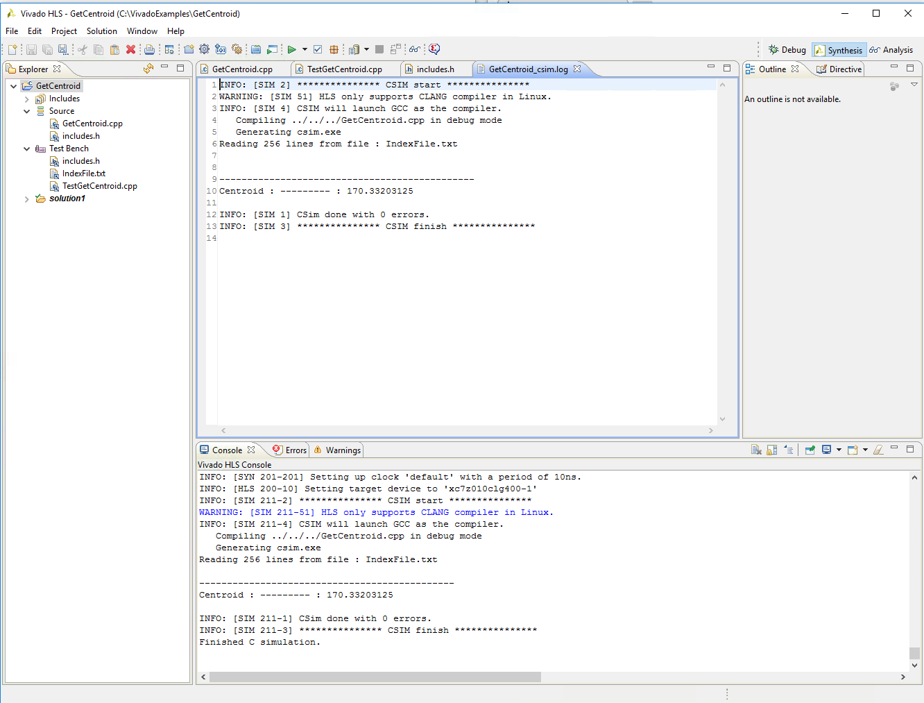
Success! This shows that our HLS executable successfully read the input file, populated the array and stream, and ran the algorihtm like it was supposed to. It got within about 0.001 of the true centroid value. Don't get too excited, though. It hasn't simulated running the algorithm on the board you specified yet. We'll do that in the next subsection.
If you get an error, the most likely issues are probably related to pointing HLS to your source files. Go back to Part 1 and make sure that all your input files are properly shown in your Simulation Settings, and that those input files are in the project directory (note that HLS will create some auxiliary directories and copy these input files to them eventually).
1.3.3: A C/RTL Simulation of GetCentroid in the Test Bench
The next step is to simulate how the algorithm will run on the Zynq 7010. To do this, click on Synthesis (the little green arrow) and wait until that finishes. Ignore the output for now. We'll go over that later. Then click on the Run C/RTL Cosimulation button, which is the little check box in the top toolbar. For now, we'll just click OK with all the defaults as they are.
I don't know all the secrets, but Vivado HLS basically has an emulator that crunches the numbers like it would if it was using DSPs, registers, etc. It will report some timing information, and also report the result it gets using the emulator. Don't trust the timing information. In my experience, it's usually way off. You should see the same value of 170.332... for the Centroid result. If you don't, something is wrong.
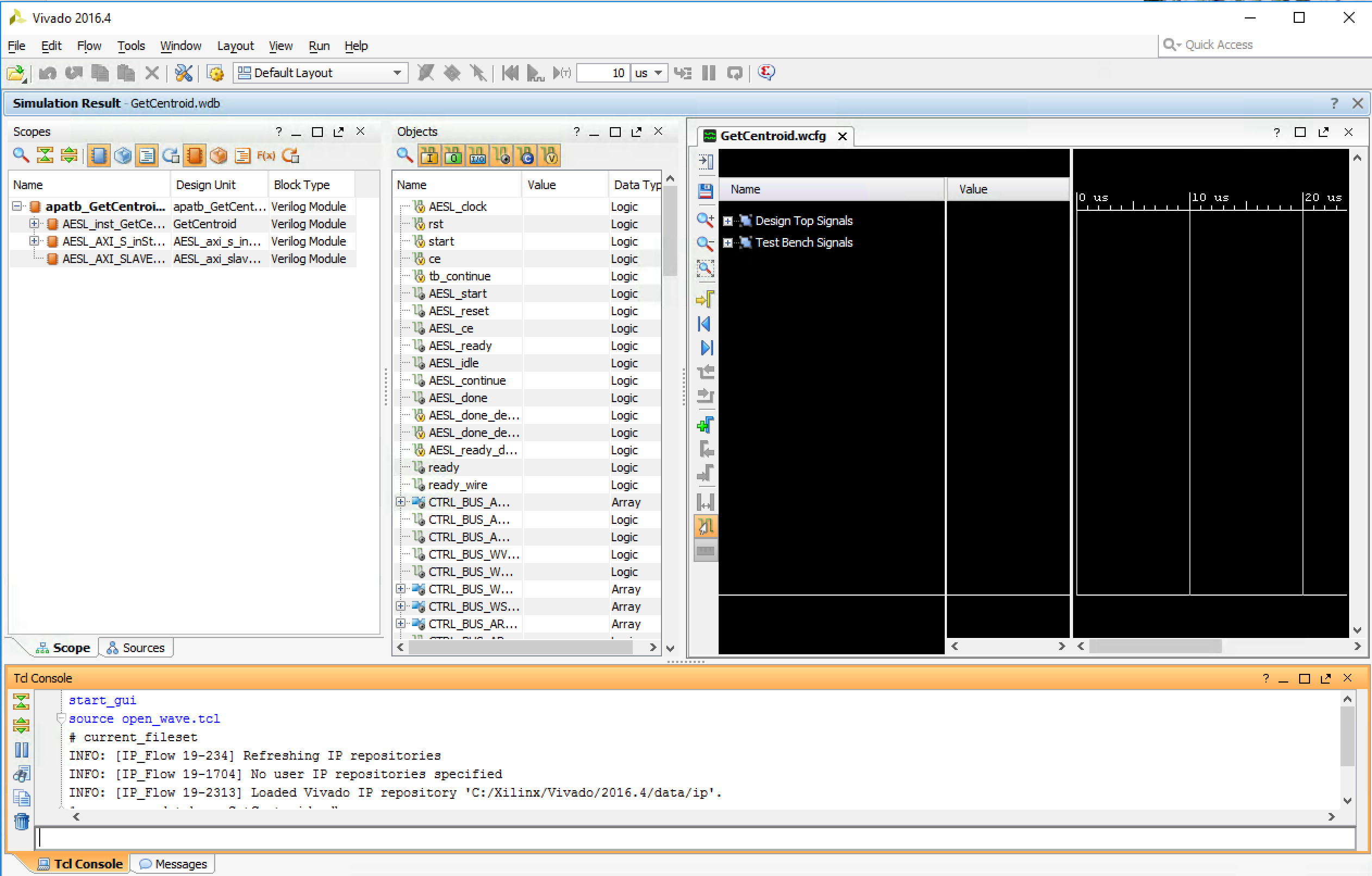
One neat thing you can do here is generate the waveforms to see exactly how your design behaves on a clock-cycle by clock-cycle basis. If you're not in a hurry, you can run the co-simulation again with the Verilog/VHDL Simulator Selection set to Vivado Simulator and Dump Trace set to All. After the co-simulation is finished, you should see the little wavy icon on the top toolbar go from grayed-out to colored-in. If you click this Open Wave Viewer icon, you'll see something like this
It's definitely worthwhile to poke around a bit in this interface to see what your Design Top Signals and Test Bench Signals are doing while the algorithm is running. For instance, we can look at how our IndArr is being handled on a bit-by-bit basis by looking at all the associated control signals and data signals, as in the following view:
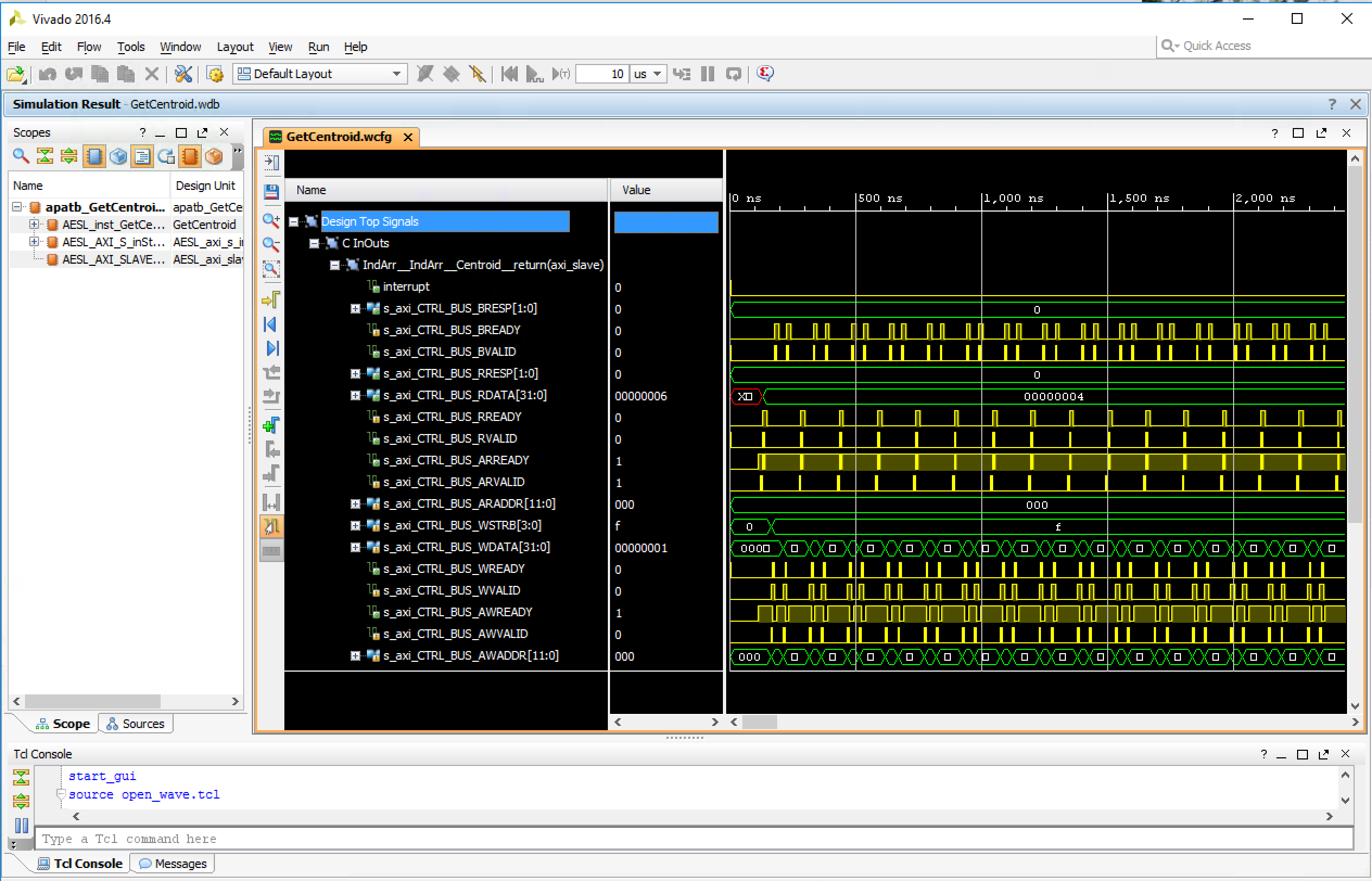
Ain't that sweet? It's like you have your own little oscilloscope living in the computer! This waveform viewer can be EXTREMELY helpful in debugging your IP core later on. Right now, we're going to synthesize that IP core.
← Previous ... Next →