Table of Contents
2.2: Synthesis, Implementation, and Creating A Bitstream in Vivado Design Suite
This section is going to describe how to synthesize and implement the block design you just created, and then turn it into a bitstream we can load into the Programmable Logic. To do this, you'll need to follow the steps below.
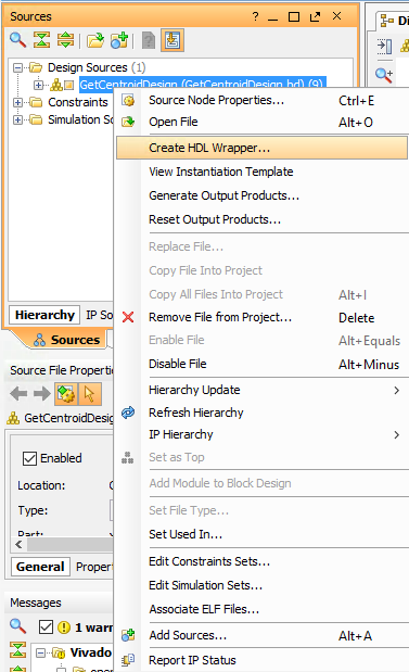
1) Create an HDL Wrapper
Right-Click on the top block in the Design Sources folder (under the Sources tab) and select "Create HDL Wrapper" as shown below.
Select "Let Vivado manage wrapper and auto-update". The HDL wrapper will create a Verilog file that specifies all the inputs and outputs of the design, and allows Vivado to synthesize the it properly.
2) Synthesize the Project
In the Flow Navigator (the left hand panel of the Vivado GUI), click Synthesis → Run Synthesis and simply select OK on the window that pops up. If you're not familiar with the concept of synthesizing a design, you can read a bit more about it
here. When it's finished, you have the option
of opening the synthesized design or running the implementation right away. I think it's worthwhile to do the former and explore things if you're not familiar with all of the features in Vivado Design Suite.
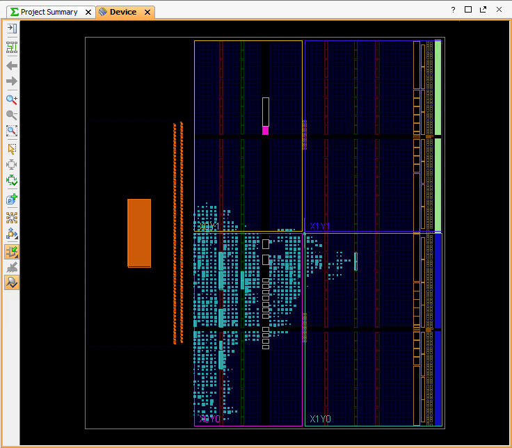
3) Implement the Project
In the Flow Navigator, click Implementation → Run Implementation and select OK. This will actually lay your design down on the chip. It's definitely worth opening the implemented design after it's finished so you can see how many resources it's eating up. For a little more insight into implementation, you can see another tutorial I wrote. It's kind of cool to see all the logic that makes up your design.
4) Generate the Bitstream
In the Flow Navigator, click Program and Debug → Generate Bitstream and select OK. Once that's finished, click Cancel. Now we have a .bit file that we can load into the FPGA to realize our design on the chip. Here's a pretty good description of what the bitstream is and how it's used if you're not sure.
5) Program the Bitstream
First of all, make sure that you're hooked up to your MicroZed with either a JTAG device or the USB cacble.
In the Flow Navigator, click on Open Target under the Harware Manager in the Program and Debug
section. Click on Open New Target and then keep clicking Next until you reach the Finish
button.
Vivado should automatically find your MicroZed board under localhost and you should see a window like the one below. You can right-click xc7z010_1 and select Program Device.
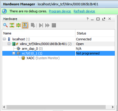
If everything worked, you should see the blue LED on your MicroZed light up. You should also see the status go from "Not programmed" to "Programmed" in the Hardware Manager. Congratulations, you just loaded your design onto the PL of the Zynq7010!
6) Export the Bitstream
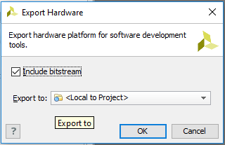
So now we have programmed the FPGA on the Zynq7010 with our design, but we still need to write some code for the ARM processor so that it can receive data over Ethernet, DMA it into our algorithm (from DDR into the IP), and then read the results out of the output register. To do that, we're going to export our design to Xilinx SDK by clicking File → Export → Export Hardware . Make sure to check the "Include bitstream" box. That way we can load the bitstream directly from SDK.
7) Launch SDK
Now, click on File → Launch SDK to bring up the Xilinx Software Development Kit. When it first starts, SDK shows the hardware defintion file (system.hdf) for your design. This is pretty cool stuff. You can examine it and see the memory mapped registers for all the various peripherals.
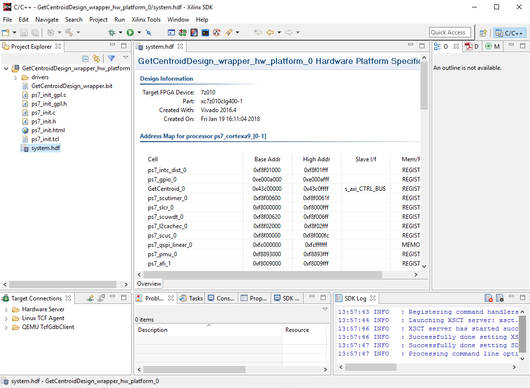
If the memory map is confusing to you, don't worry too much. Hopefully it'll become more clear when we actually look into the registers that SDK has created for our GetCentroid algorithm.
In the next chapter, we'll go over how we program the ARM processor with its own instructions so we can send some data over Ethernet and run it through the algorithm that we've built on the chip.
← Previous ... Next →