2.0 Creating The Project In Vivado
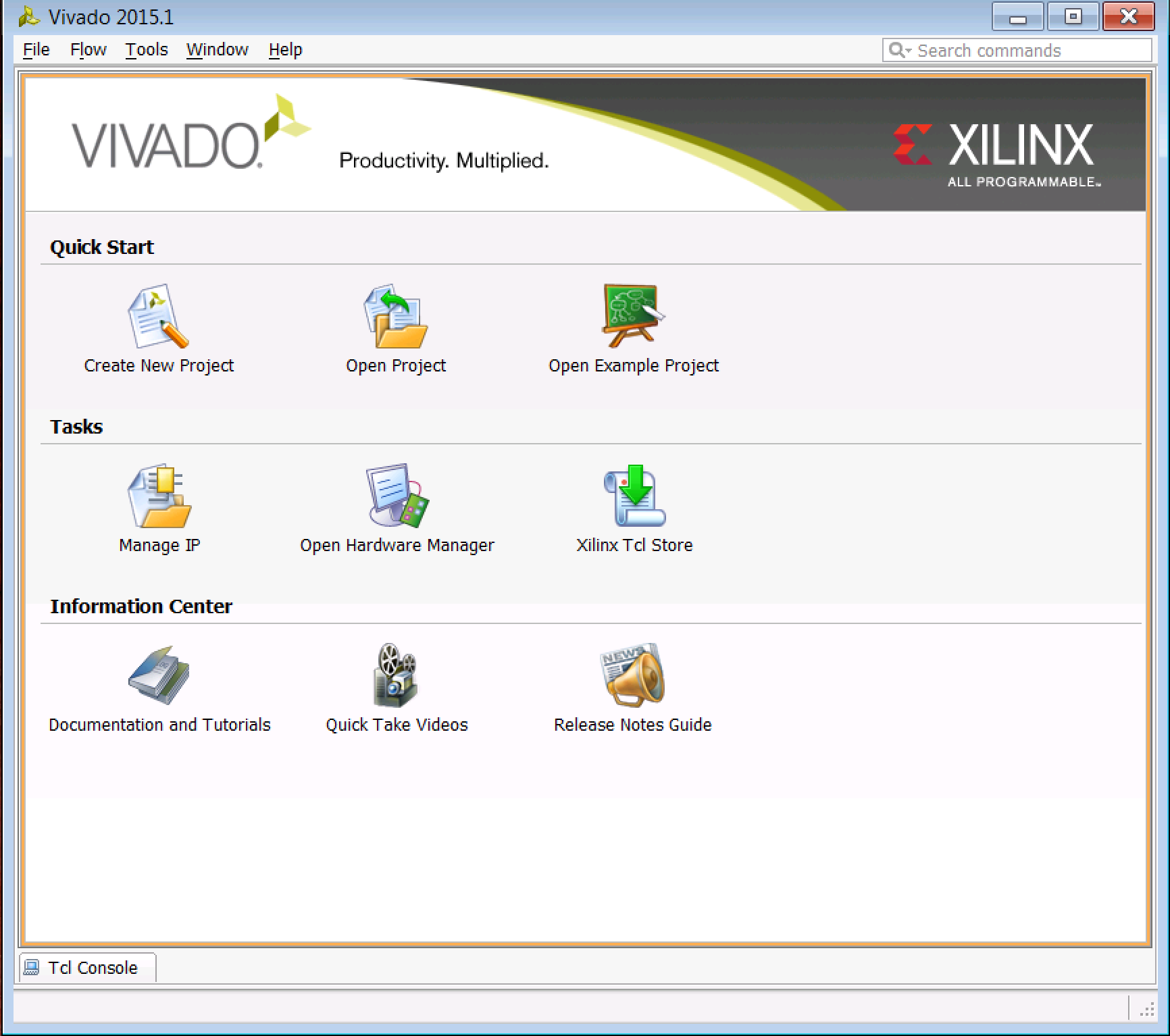
The first thing we need to do is create a new project in Vivado (I'll be using Vivado 2015.1, but your version will likely differ). Start Vivado by either double-click on the Vivado 2015.1 desktop icon or going to Start →Xilinx Design Tools→Vivado 2015.1→Vivado 2015.1. You should see the following pop-up screen.
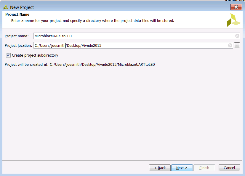
When the New Project window pops up, click Next. You will see a New Project window pop up. Enter the following:
- Project name: MicroblazeUARTtoLED
- Project location: the directory where you want to keep the project files and subdirectories
- Keep the Create project subdirectory box checked so that Vivado creates a new directory
The window should look like this (your username probably won't be joesmith):
In the Project Type window, select RTL Project, and keep the Do not specify sources at this time box checked, as we won't be using any RTL source code in this application.
The next window that pops up is the Default Part window. Here you can specify a particular Xilinx FPGA type or a particular development board offered by Xilinx. The beauty of this is that Vivado will know all the details about your target environment, i.e. the pinout of your particular package, the number of banks, etc. For our case, we're going to be using the VC707 board, so click on Select: Boards and you should see the option for the VC707 board. Select it.
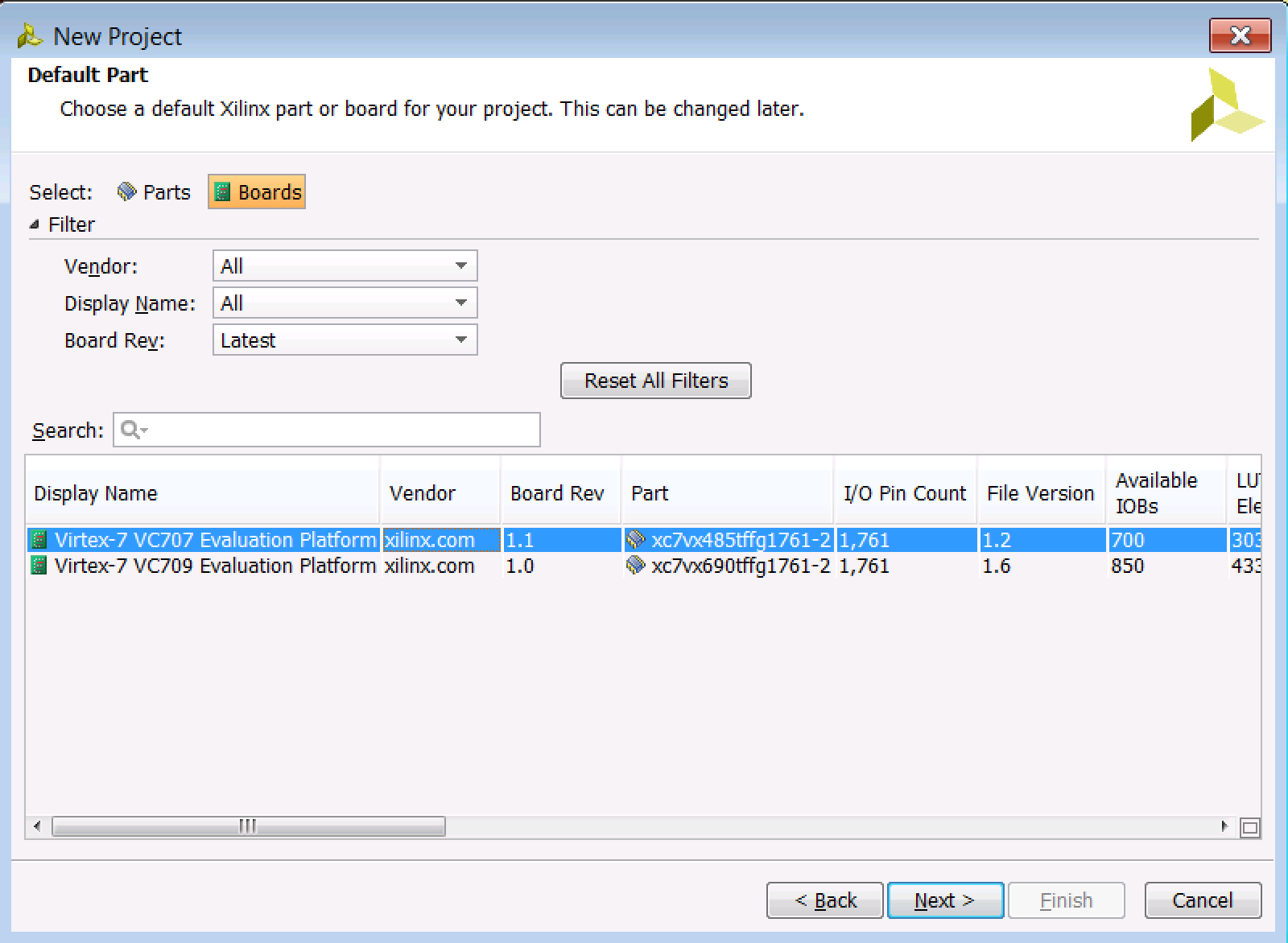
If you're using a different board from the VC707, don't fret. You should still be able to follow along with this tutorial since Vivado is smart enough to know the pin locations for the various peripherals we'll be using. Just select your board and continue with the tutorial.
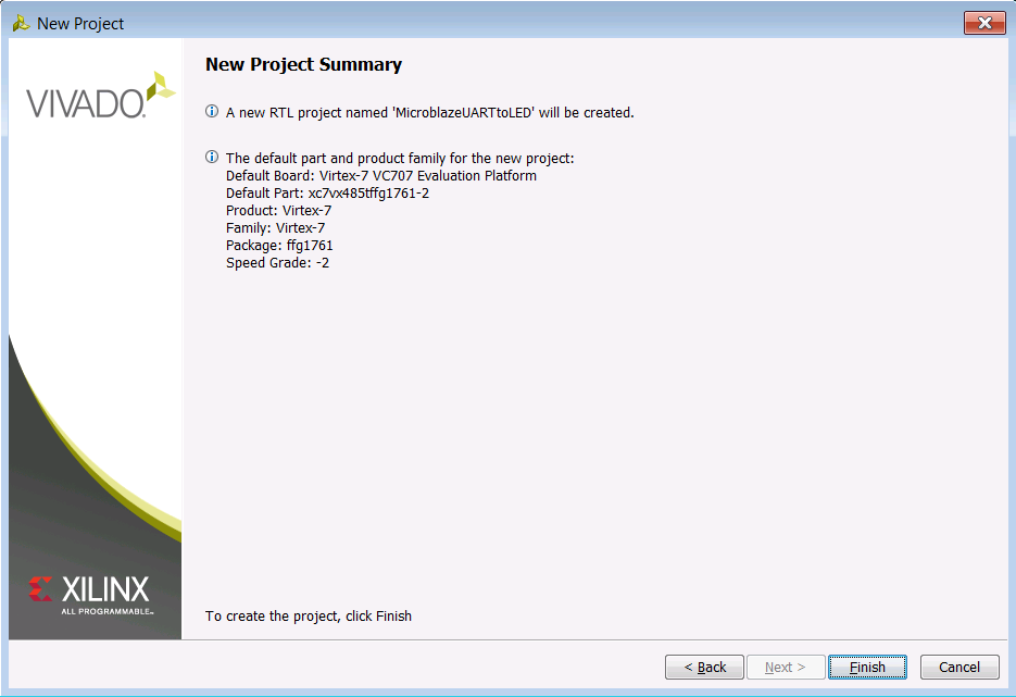
Click Next. If you got everything right, you should see the following information on the New Project Summary screen:
You should get a little status bar telling you that Vivado is building your project, and after a few second, your new project window pops up:
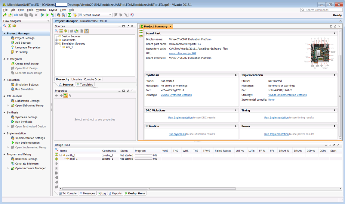
Now, we have a pretty blank slate here since we haven't specified any sources. We aren't really going to be writing any code here, in fact. What we're going to do is create a block design and have Vivado write its own HDL wrapper for us. So the next step is to click Create Block Design. You're welcome to name your design whatever you want, but for convenience I am mimicking the project name. Here are the entries for the window that pops up:
- Design name: MicroblazeUARTtoLED
- Directory: Local to Project
- Specify Source Set: Design Sources
After pressing OK, you will now have a file called [Project Dir]\MicroblazeUARTtoLED.srcs\sources_1\bd\MicroblazeUARTtoLED\MicroblazeUARTtoLED.bd, which is an XML file that represents your block design. As you can see from the diagram in the central window, our design is empty. So the next step is to add some components!
← Previous ... Next →
Table Of Contents
- Part 1: Getting Started
- Part 2: Creating the Project in Vivado
- Part 3: Creating the Block Diagram
- Part 4: Building the Application in SDK
- Part 5: Running the Application in SDK