The Many Different Ways to Describe a GPIO on the TX2/TX2i with Linux
I just spent an hour or so feeling like my head was spinning in circles while trying to understand the /dev/mem register address mapping for a particular GPIO on the TX2i. There are so many numbers and labels used to describe a pin, and the way those numbers and labels are encoded was not immediately clear to me.
Why was I trying to use /dev/mem to control the GPIO instead of just using sysfs or libgpiod, you ask? Well, because the good ol' techniques of using export /sys/class/gpiochip### and libgpiod calls just weren't cutting it for my intended purpose. I was trying to toggle a GPIO about 30,000 times a second, but the results of my tests just weren't making sense. When I hooked up an oscilloscope, what I saw perplexed me: the fastest I could drive a GPIO low then high using libgpiod was about 250 microseconds!!!.
So I set out on the task of trying to drive the GPIO with direct register access on the TX2i using /dev/mem. Below I will show you the stepping stones and procedures I eventually found to do this after sifting through the vastness of the NVidia forums.
The Starting Point: Finding Your GPIO Pin's Port and Offset
The first step on the road to controlling a GPIO on the TX2 is to figure out which pin it corresponds to and what it's called. Nvidia provides a PinMux Spreadsheet that allows us to do exactly that.
As an example, let's say I wanted to use the SPI1_CLK pin on our development board (G13) to drive an interrupt on a microcontroller. The spreadsheet entries for this pin are shown in the following image.
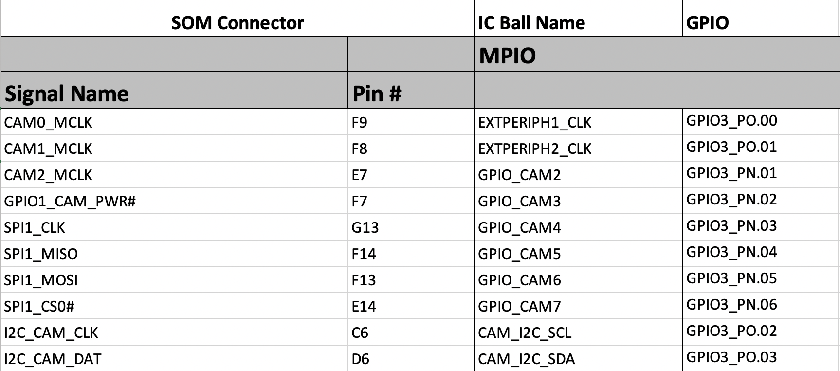
What we see for the SPI1_CLK row are the following:
- Column 1 shows the generic signal name of the pin we are looking for: SPI1_CLK. This name indicates what functionality the pin has when used in the High Speed Input configuration (at least that's what I can gather from the technical refernece manual.)
- Column 2 shows the pin# corresponding to this signal on the TX2 Samtec 400-pin connector.
- Column 3 gives the PADCTRL name for this pin. This name can be used to lookup the control registers for the associated pin in Section 8.31 of the TX2 Technical Reference Manual.
- Column 4 shows the GPIO Port and Offset for the pin. They are encoded as:
GPIO3_P[Port Letter].[Offset]
In the case of SPI1_CLK, this would be: Port Letter=N, Offset=3.
I am not sure why they use the "3" in GPIO3, but these ports/offsets correspond to the GPIO_Main controller on the TX2. There is also a GPIO_AON controller, but we won't touch on that here.
As we'll see in the next section, getting the Port Letter/Label and the Offset are the key to finding the sysfs#, libGPIO number, and register address.
Finding the sysfs# (Also the gpio# In Some Documentation)
Perhaps the easiest way to toggle a GPIO from the command line is using the simple method of the sysfs interface (/sys/class/gpio). To find the available sysfs numbers, the dmesg command once again proves to be one of the most useful things development. We can find the mapping by typing sudo dmesg | grep "registered GPIO".
root@tegra-ubuntu:~/Globetrotter/CCU/demo$ dmesg | grep "registered GPIO"
[    0.446830] gpiochip_setup_dev: registered GPIOs 320 to 511 on device: gpiochip0 (tegra-gpio)
[    0.450589] gpiochip_setup_dev: registered GPIOs 256 to 319 on device: gpiochip1 (tegra-gpio-aon)
[    0.536297] gpiochip_setup_dev: registered GPIOs 248 to 255 on device: gpiochip2 (max77620-gpio)
[    0.637755] gpiochip_setup_dev: registered GPIOs 232 to 247 on device: gpiochip3 (tca9539)
What we see in the above printout is that the GPIOs in our GPIO_Main controller (tegra-gpio) range from 320 to 511. If you do the math, this is 192 total GPIOs. Digging deeper into the documentation, you'll find there are 24 ports and 8 GPIOs per port, yielding 24*8=192 GPIOs.
So how do we find the sysfs# for a particular port/offset? Well, there is a formula given in the tegra1860-gpio.h header file that tells us how to do this. The relevant portion of that code is shown in the image below.
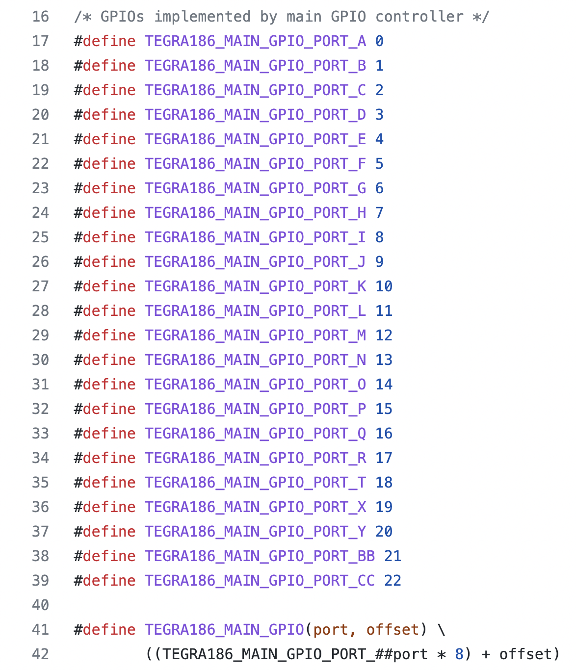
As you can see near the bottom, there is a formula that gives us the TEGRA186_MAIN_GPIO number. To get the sysfs#, we simply add the base number to that as so:
Going back to our SPI_CLK1 example, we find that sysfs# = 320 + 13*8 + 3 = 427.
Toggling GPIO427 From the Command Line Using the sysfs#
If we want to toggle the GPIO with sysfs# 427, we'd simply do something like:
$ cd /sys/class/gpio/
$ sudo sh -c "echo 427 > export"

$ sudo sh -c "echo out > gpio427/direction"

$ sudo sh -c "echo 1 > gpio427/value"
Note the use of "sh -c" here prevents us from getting the permission denied message.
Changing the PinMux Configuration to Use a Pin as a GPIO
In some cases, the pin you're trying to use as a GPIO may not available for use. It may be set up to be used as a Special Function Input/Output (SFIO) in the pinmux configuration. Note the TX2 Technical Reference Manual also refers to this as an HSIO in some cases.
To check how the pinmux configuration for your pin is set, you can check the tegra_pinctrl_reg file.
$ sudo cat /sys/kernel/debug/tegra_pinctrl_regAnd here is where the PADCTRL column in the PinMux spreadsheet pays off. We can use that label to find the entry we're interested in. For SPI1_CLK, this was "GPIO_CAM4". With a little bit of case-change digging, we can find the associated pinmux register for SPI1_CLK.
root@tegra-ubuntu:/# cat /sys/kernel/debug/tegra_pinctrl_reg  | grep cam4
Bank: 0 Reg: 0x02430038 Val: 0x00000000 -> gpio_cam4_pn3
This shows us that our pinumux register address for SPI_CLK1 is 0x02430038 and its current value is 0x00000401.
To understand what that 0x00000401 means, we can turn back to the TX2 Technical Reference Manual and do a search for GPIO_CAM4. We see that in Section 8.31.9.15, the bitfields of the register are defined. In our case, the 0x401 means that the pin is currently designated to be used as a HSIO (High Speed Input/Output or Special Function Input/Output) since bit 10 is set. We want that bit to be cleared so that it is enabled as a GPIO instead, meaning we want the register to have a value of 0x1.
If you want this to be a permanent change, you'll have to change your tegra186-mb1-bct-pinmux-quill-p3310-1000-[BOARDREV].cfg file and reflash the device (which is beyond the scope of this tutorial). But if you just want to change it temporarily, you can use devmem2 (available with a simple apt-get command). All we need to do is type:
$ sudo devmem2 0x02430038 w 0x1Note that we can also read back the value of the register using sudo devmem2 0x02430038. Now we should be good to drive this pin as a GPIO output!
Accessing the GPIO Using libgpiod
If we want to get a bit fancier and drive our GPIO from a C/C++ program in an elegant fashion, we either use our sudo dmesg | grep "registered GPIO" command or we can do a sudo cat /sys/kernel/debug/gpio and get the following output.
gpiochip3: GPIOs 232-247, parent: i2c/0-0077, tca9539, can sleep:

gpiochip2: GPIOs 248-255, parent: platform/max77620-gpio, max77620-gpio, can sleep:
 gpio-248 (                    |external-connection:) in  hi
 gpio-253 (                    |spmic_gpio_input    ) in  lo
 gpio-254 (                    |spmic_gpio_input    ) in  hi

gpiochip1: GPIOs 256-319, parent: platform/c2f0000.gpio, tegra-gpio-aon:
 gpio-272 (                    |temp-alert          ) in  hi
 gpio-312 (                    |Power               ) in  hi
 gpio-313 (                    |Volume Up           ) in  hi
 gpio-314 (                    |Volume Down         ) in  hi

gpiochip0: GPIOs 320-511, parent: platform/2200000.gpio, tegra-gpio:
 gpio-412 (                    |vdd-usb0-5v         ) out lo
 gpio-413 (                    |vdd-usb1-5v         ) out lo
 gpio-420 (                    |eqos_phy_reset      ) out hi
 gpio-444 (                    |wp                  ) in  lo
 gpio-445 (                    |cd                  ) in  lo
 gpio-446 (                    |en-vdd-sd           ) out hi
 gpio-479 (                    |external-connection:) in  hi
This shows us the mapping of the sysfs numbers to the gpiochip# space, which we need when using libgpiod. For example, let's say that we know the GPIO we want to toggle our SPI1_CLK pin with sysfs#=427. Well, that number falls in the range of 320 to 511, which corresponds to gpiochip0. To find the line number, all we have to do is calculate the offset from the 0th sysfs number for that chip. In this case, it's 427-320=107. Also note the address of 0x2200000 that the gpiochip0 registers start at. This will be important for the next section.
To access the GPIO from our C/C++ code, we would set it up as follows:
#include <gpiod.h>

struct gpiod_chip *gpChip;

struct gpiod_line *gpLine;


// Our main code goes here...
int main(){

  ....

  // And here we set up the GPIO in question
  gpChip = gpiod_chip_open_by_name("gpiochip3");

  gpLine = gpiod_chip_get_line(gpChip, 107);

  ...

}
After this we could make some calls like gpiod_line_request_output(gpLine, "gpLine", 0); and gpiod_line_set_value(gpLine, 0); to set that GPIO low.
Accessing the GPIO Using /dev/mem
Now for the final step in the process. To find out what the address of the GPIO Enable_Config register for the particular GPIO we are after is, we turn to Section 8.30.9 and Table 79 in the TX2 Technical Reference Manual.
In Table 79, we see the ENABLE_CONFIG registers for all the accessible GPIO Ports. Since we are interested in the main controller, we go to the section that starts with GPIO Registers (base address 0x02200000). Then we look for the cells for Port N, which starts at offset 0x10000. Since we are using Port N, Offset 3, we use the value of 0x10060 for GPIO_N_SCR_03_0.
Once we have the GPIO config register and the PADCTRL registers, we can use the nifty code written by ajcalderont to toggle the GPIO. I've copied my own version of this for the SPI1_CLK GPIO below. Note that the shortest duration of sleep we can feasibly achieve using usleep or nanosleep or any other thread sleeping calls is about ~50 microseconds from userspace on the TX2.
#include <stdio.h>
#include <stdlib.h>
#include <stdint.h>
#include <unistd.h>
#include <sys/fcntl.h>
#include <sys/mman.h>

#define GPIO_427    0x02210060 // N.03 GPIO address
#define SPI1_SCLK   0x02430038 // Control pad register address

#define GPIO_ENABLE_CONFIG 0x00
#define GPIO_OUTPUT_CONTROL 0x0c
#define GPIO_OUTPUT_VALUE 0x10

int main(void) {
  int fd = open("/dev/mem", O_RDWR | O_SYNC);
  if (fd < 0) {
    perror("/dev/mem");
    fprintf(stderr, "Please run this program as root (for example with sudo)\n");
    exit(1);
  }

  uint32_t pagesize = getpagesize();
  uint32_t pagemask = pagesize - 1;

  void *gpio_address = mmap(0, pagesize, PROT_READ | PROT_WRITE, MAP_SHARED, fd, (GPIO_427 & ~pagemask));
  void *pad_ctl_address = mmap(0, pagesize, PROT_READ | PROT_WRITE, MAP_SHARED, fd, (SPI1_SCLK & ~pagemask));

  if (gpio_address == NULL || pad_ctl_address == NULL) {
    perror("mmap()");
    exit(1);
  }

  volatile char *gpio_base = ((char *)gpio_address + (GPIO_427 & pagemask));
  volatile char *pad_ctl = ((char *)pad_ctl_address + (SPI1_SCLK & pagemask));

  *pad_ctl = 0x00000001; // Select GPIO

  *(gpio_base + GPIO_OUTPUT_CONTROL) = 0x00000000; // Driven
  *(gpio_base + GPIO_ENABLE_CONFIG) = 0x00000003; // GPIO Enable, Out

  uint32_t val = 0x00000001;
  volatile char *output_value = gpio_base + GPIO_OUTPUT_VALUE;

  // Note that we can sleep for a minimum of ~50 microseconds using sleep calls.
  // If we want shorter duration, we need to use simple while loops and/or make
  // this a kernel module
  for(int i=0; i<10000; i++) {
    usleep(100);
    val = val ^ 0x00000001;
    *output_value = val;
  }

  *output_value = 0x00000000;

  munmap(gpio_address, pagesize);
  munmap(pad_ctl_address, pagesize);
  close(fd);

  return 0 ;
}