4.0 Launching the Project in SDK
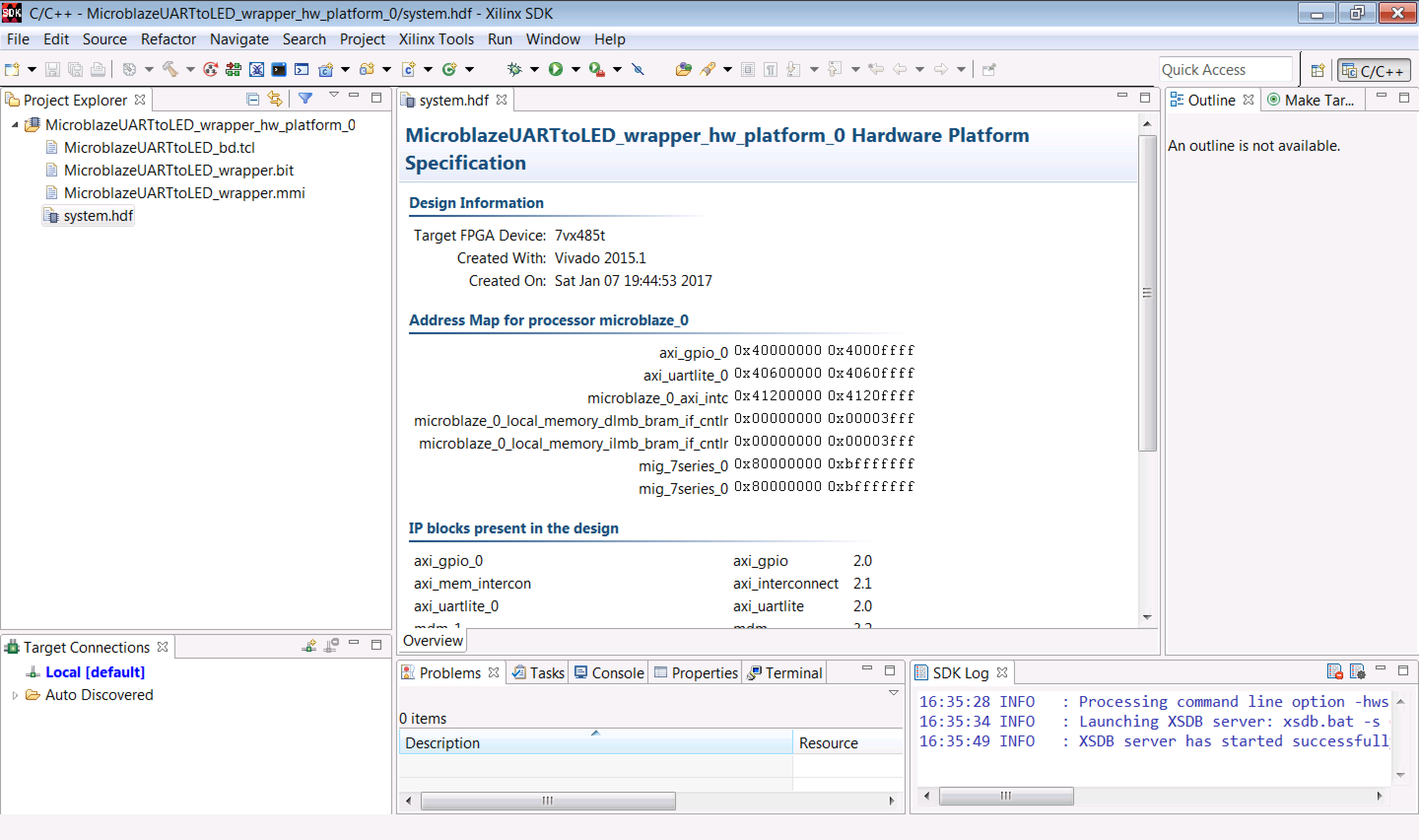
After launching the SDK, you should see a window that shows all the information about the hardware setup we've created. For instance, we see the address space of the GPIO and UART, as well as the version of each piece of IP we've used below that:

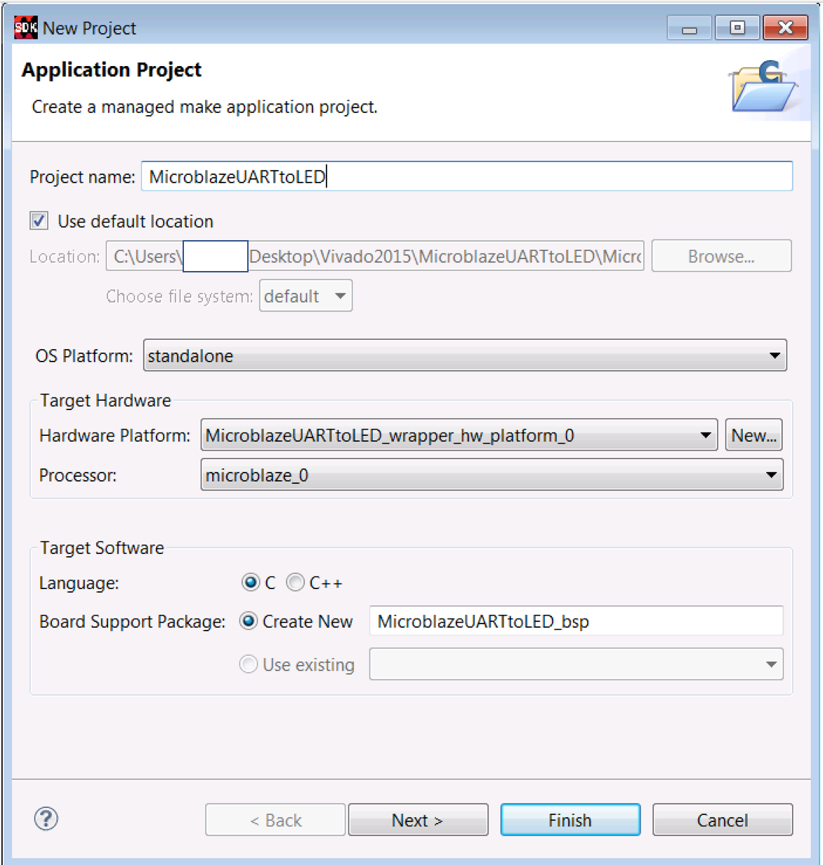
Click on File -> New -> Application Project and configure things like so:

We're going to use the same name for the SDK project as we used for the HDL project in Vivado, and we'll to do a standalone state machine that we'll write in C. Click on Next, and in the New Project window, select Empty Application and click Finish. The SDK will take a little while to import all the source files and libraries it needs to support the hardware we've created in the Microblaze.
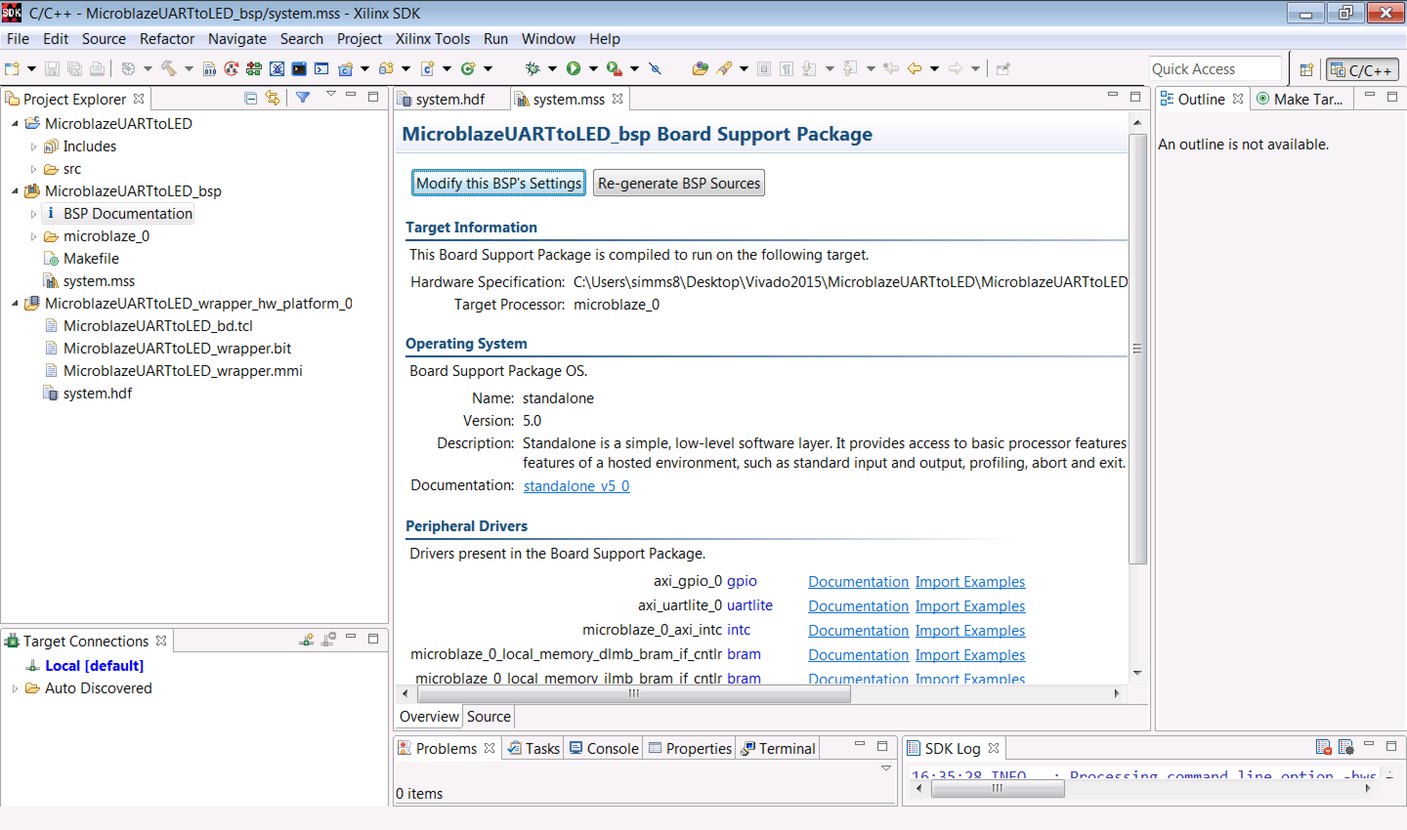
Take a little while to go through the BSP Documentation window and other subfolders under the MicroblazeUARTtoLED_bsp folder. There's a lot of useful stuff in here. You can click on any of the Documentation and Import Examples links and you'll find some examples of how to write C code that makes use of the hardware we've built in our block design. The include, lib, and libsrc folders also have a bunch of headers and source files that can be of great use when trying to figure out how to write code for the Microblaze.

4.1 Writing the Application
The next step is going to be to actually generate our .ELF file, and to do this, we'll need a main(), along with a bunch of supporting functions. The code we're going to be using is located in this main.c file.
After you've downloaded main.c, open it in the SDK by going to File -> Open File and selecting the file. Then save it in the MicroblazeUARTtoLED.sdk/MicroblazeUARTtoLED/src/ directory located in your main project directory. You should see it show up in the src folder under the main MicroblazeUARTtoLED folder in the Project Explorer on the left hand pane of the SDK. If you've run all the previous steps correctly, the file should compile and link without any problem. It's probably worth going through the code a little bit to help clarify what's going on, though.
4.1.1 Preamble
The preamble of the file consists of the following include statements:
		    #include "xparameters.h"

		    #include <xil_printf.h>

		    #include <stdio.h>

		    #include "xil_exception.h"

		    #include "xuartlite.h"

		    #include "xintc.h"

		    #include "xgpio_l.h"
xparameters.h is a standard include file for all the Microblaze applications since it contains identifiers for driver configurations and the memory map.
xil_printf.h is the header file that allows us to use the xil_printf() function. I will warn you right now, it's not even worth trying to use the regular printf() function since the SDK doesn't know how to interpret the standard C format codes. So just go with xil_printf() if you want to print something to stdout.
xil_exception.h contains the identifiers for code that will be used if your program takes a crash into la-la land (if you try to divide by zero, for instance.
xuartlite.h, xintc.h, and xgpio_l.h are the header files for the UART, interrupt controller, and low-level GPIO drivers, respectively.
After these includes come some #define statements, function protoypes, and global variable definitions. It should be pretty clear what the functions do based on their names. Xilinx has done a good job making easy-to-use structures like the XUartLite, so you'll notice pointers to it being passed around in the various functions. We're going to make our instance of the interrupt handler (XIntc) store all of the bytes received over the UART in the ReceiveBuffer.
4.1.2 main()
Our main() is extremely simple. It's a finite state machine that simply waits for a new character to be received over the serial port. When it does, it checks the byte to see if it's an a or a b. If it's the former, it'll toggle all the LEDs to either on or off. If it's the latter, it'll prompt the user for another character and then it'll put the 8-bit representation of that character on the 8 LEDs. If it's neither, it'll complain.
Before entering the state machine, the program will print out the configuration of the serial port (we're using 9600 baud, which was the default choice back in the block design).
← Previous ... Next →
Table Of Contents
- Part 1: Getting Started
- Part 2: Creating the Project in Vivado
- Part 3: Creating the Block Diagram
- Part 4: Building the Application in SDK
- Part 5: Running the Application in SDK