3.0 Taking a Look At The Source Code
At this point, I think it's beneficial to take a look at the source code to see what we're trying to do and how we're trying to do it.
3.1 The Top Level File: clocked_led.vhd
The file clocked_led.vhd is the top level file. If you're a C/C++ programmer, this is kind of like the file that holds main(). Vivado does a good job of illustrating this in its hierarchical view. It's worth playing around with the "Sources" view in the Project Manager and inspecting how Vivado organizes the files in the Hierarchy, Libraries, and Compile Order views.
3.1.1 Library Includes
If you open the clocked_led.vhd file up, you'll see the following lines near the top:
                library IEEE;

                use IEEE.STD_LOGIC_1164.ALL;

                use IEEE.numeric_std.all;


                library UNISIM;

                use UNISIM.VComponents.all;
If you're new to VDHL, these are include directives for a standard set of libraries, similar to #include <stdio.h> in C. The IEEE libraries define operators, data types, functions, and all of that good stuff. Take a look at The IEEE Libraries And Examples Using Functions if you're curious about all this.
3.1.2 Entity Definition
The next few lines are where the real magic starts.
                entity clocked_led is

                       Generic (CLOCK_RATE : integer := 200_000_000

                                       );

                       Port (                            clk_pin_p     : in  STD_LOGIC;

                             clk_pin_n     : in  STD_LOGIC;

                             rst_pin       : in  STD_LOGIC;

                             led_pins      : out STD_LOGIC_VECTOR (7 downto 0)

                               );

                end clocked_led;
This is our definition of the design in a nutshell. As you can see it's pretty simple. A differential clock with a frequency of 200 MHz and a reset button are the inputs, and the outputs are eight LEDs. A lot of RTL tutorials will compare this to the simple pin-definition in the datasheet of an electrical part.
3.1.3 Behavioral Section
The next set of lines delve a little bit deeper into the "schematic". The Behavioral declaration shows some of the individual components in our design. I like to think of the component definitions like class definitions in C++. They define the blueprint for a data type. Later down in the code, we see the equivalent of instantiating some "objects".
                architecture Behavioral of clocked_led is


                     --

                     -- module definitions

                     --

                     component led_ctl is

                         Port (                                rst_clk_rx                                  : in  std_logic;

                                   clk_rx                      : in  std_logic;

                                   led_o                   : out std_logic_vector(7 downto 0)

                          );

                     end component led_ctl;


                     component meta_harden is

                         Port (                                clk_dst                : in  std_logic;

                                   rst_dst                : in  std_logic;

                                   signal_src                         : in  std_logic;

                                   signal_dst                         : out std_logic

                          );

                     end component meta_harden;


                     component clk_core is

                         Port (                                clk_in1_p                      : in  std_logic;

                                   clk_in1_n                      : in  std_logic;

                                   clk_out1                   : out std_logic

                          );

                     end component clk_core;


                     -- clock and controls

                     signal rst_i, rst_clk_rx                                                                      : std_logic := 'U';

                     signal clk_i, clk_rx                                                          : std_logic := 'U';

                     signal rxd_i                                  : std_logic := 'U';

                     signal led_o                                  : std_logic_vector(7 downto 0) := (others=>'U');


                     constant vcc                                  : std_logic := '1';

                     constant gnd                                  : std_logic := '0';
Note that each of the component modules have names that match the names of our input VHDL files (except clk_core). That's no coincidence. Vivado knows how to represent the led_ctl and meta_harden components because it has VHDL source files that define them. However, we don't have an input file for clk_core yet. We are going to have to create that later on using some IP from the IP Wizard.
You will also notice some digital logic levels and signals being defined near the end. This site gives some definitions of the various std_logic types.
3.1.4 Instantation
The next section will take care of instantiation. It will create actual "parts" in our construct. First take a look at the lines that define the intput and output buffers:
                     --

                     -- define the buffers for the incoming data, clocks, and control

                     IBUF_rst_i0:         IBUF         port map (I=>rst_pin, O=>rst_i);


                     --

                     -- define the buffers for the outgoing data

                     OBUF_led_ix: for i in 0 to 7 generate

                          OBUF_led_i: OBUF port map (I=>LED_o(i), O=>LED_pins(i));

                     end generate;
The first line declares an input buffer (IBUF) with the name of IBUF_rst_io that takes the rst_pin input, buffers it, and puts out rst_i. The IBUF data type is defined in the UNISIM library. Take out the line that includes the UNISIM library at the top of the file, and you'll get an error.
The OBUF (output buffer) primitive type is defined in the UNISIM library as well. You can find a list of all the primitive types defined in the library here. The three lines to instantiate the OBUF_led_i are a bit fancier. This is a condensed way to create 8 different instances of the the OBUF primitive type. They will essentially turn out as an array of OBUF_led_ix[7:0] once we've synthesized our design. The inputs will be LED_o[7:0] and the outputs will be LED_pins[7:0].
Now, if you're getting ahead of the game and trying to search the other design files for the LED_pins signals, you might be starting to wonder where they are. There are instances of "led_pins" in the clocked_led.xdc constraints file, but nowhere will you find "LED_pins". This is because VHDL is case insensitive! That's a very important point to keep in mind when writing your code.
The next few lines will create instances of the meta_harden and led_ctl components that we've defined above:
                     --

                     -- instantiate a metastability hardener for the incoming reset

                     meta_harden_rst_i0: meta_harden port map (rst_dst=>gnd, clk_dst=>clk_rx, ...

                                 signal_src=>rst_i, signal_dst=>rst_clk_rx);


                     --

                     -- instantiate the LED controller

                     led_ctl_i0: led_ctl port map ( rst_clk_rx    => rst_clk_rx,

                                                    clk_rx        => clk_rx,

                                                    led_o         => led_o

                                                  );
As you might guess, we could create any number of "meta_harden" or "led_ctl" parts here. It wouldn't necessarily make sense to do that, but in other instances you might need to create multiple "objects" for the same "class" type. Later on we'll see these object names: "led_ctl_i0" and "meta_harden_rst_i0" in the schematic representation of our code. We also see the abstract inputs and outputs assigned particular names with calls like "signal_src=>rst_i".
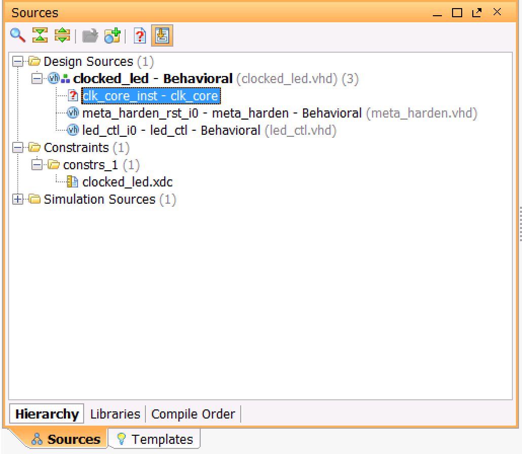
The last thing that we instantiate is clk_core_inst, which is a clk_core component. As mentioned before, we don't have a source file for this. We can see this in the Design Sources folder in the Sources window as well.
So now we'll take a little detour from the source code to create it from the IP catalog.
← Previous ... Next →
Table Of Contents
- Part 1: Getting Started
- Part 2: Creating the Project in Vivado
- Part 3: Taking a Look at the VHDL Source Code
- Part 4: Creating clk_core With the Clocking Wizard
- Part 5: Source Code for the LED Controller
- Part 6: The Constraints File clocked_led.xdc
- Part 7: Elaborating, Synthesizing, and Implementing
- Part 8: Generating and Downloading the Bitstream