4.0 Creating clk_core with the Clocking Wizard
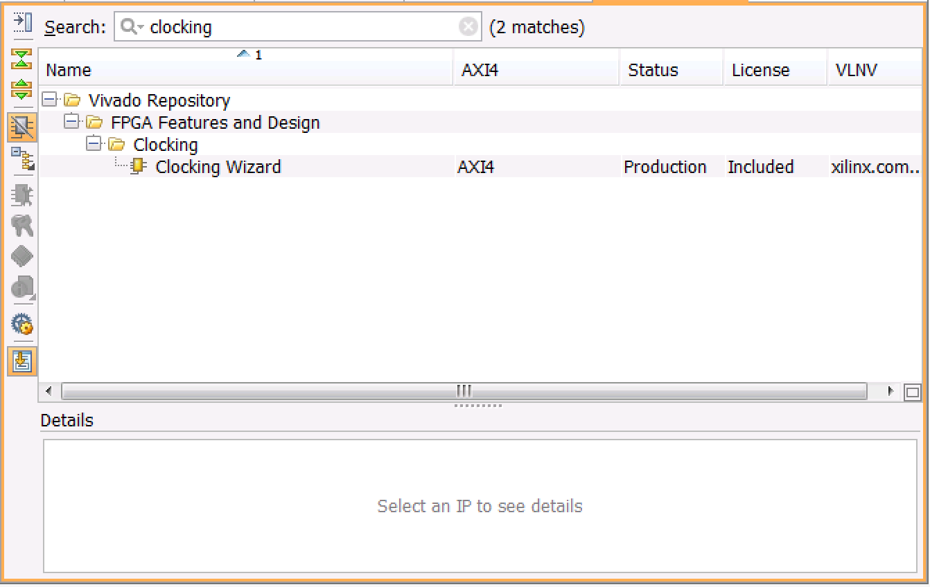
Now we'll get into our first brush with the IP Catalog. To bring it up, just click on "IP Catalog" under the Project Manager section in the Flow Navigator. That will bring up a new tab and window on the right hand side. In the Search text box, enter the word "clocking" and you should see the Clocking Wizard IP pop-up like so:

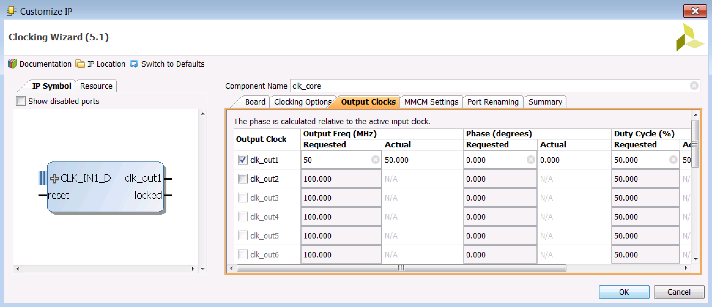
In the Clocking Wizard box that pops up, under the "Board" tab change the default values of the Component Name and CLK_IN1 (drop down):
- Component Name : clk_core
- CLK_IN1 : sys diff clock
The window should look like this:

In the "Clocking Options" tab, keep everything at its default value. We'll use the MMCM (Mixed-Mode Clock Manager) to generate the clock. The wizard knows that the input frequency of the system differential clock is 200 MHz because we set the board type to the VC707 when we defined the projected. If you're wondering where this frequency comes from, check the schematic for the VC707 and you will find the SIT9102 oscillator tuned to output 200 MHz.
Next go to the "Output Clocks" tab and set the Requested Output Frequency to 50 MHz. This will be slow enough to do some operations between each rising clock edge in the led_ctl module. However, you can also just keep it at 200 MHz if you want to see a timing error later on down the road. I mean, nobody "wants" errors, but they are definitely instructive. I'll mention this potential error later.

You don't have to change anything with the other tabs, but it's useful to see what they have to say. Click "OK" (set the Synthesis Options to "Global" on the next window) twice, and you should get a "Generate Output Products" window that tells you everything went well.
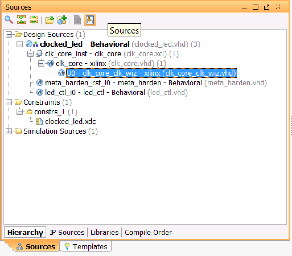
Now when you go back to the Sources window, you should see that the warning icon next to
the clk_core source has disappeared. You can expand it and get down to the source files you've
just created called clk_core_clk_wiz.vhd and clk_core.vhd (they are located in the
[project]\clocked_led\clocked_led.src\
sources_1\ip\clk_core\ directory):

We now have all of our components defined. Let's return to the source code and look at how we'll drive the LEDs with the clock we've just created.
← Previous ... Next →
Table Of Contents
- Part 1: Getting Started
- Part 2: Creating the Project in Vivado
- Part 3: Taking a Look at the VHDL Source Code
- Part 4: Creating clk_core With the Clocking Wizard
- Part 5: Source Code for the LED Controller
- Part 6: The Constraints File clocked_led.xdc
- Part 7: Elaborating, Synthesizing, and Implementing
- Part 8: Generating and Downloading the Bitstream